
Inertia in electricity systems
Industry representative: Milojko Crnkovic, ElectraNet
Moderators: Graeme Hocking, Murdoch University; Adrian Grantham, University of South Australia
Introduction
In electricity generation systems, large thermal or hydro power plants use rotating synchronous machines to generate three sinusoidal voltage phases with a frequency near 50 Hz. The electrical flux and mechanical dynamics of a synchronous generator can be modelled by well-known differential equations that depend on terms including the mechanical power being applied to the generator, the electrical load on the generator, and the moment of inertia of the rotor.
When synchronous generators are connected together, they synchronise to form a stable equilibrium. If the load on the grid increases then the increased load will be shared automatically amongst the synchronous generators in a way that maintains synchronisation. Generators with higher inertia will take a higher proportion of the additional load, and all generators will slow at about the same rate until the mechanical power applied to the generators can be increased or load can be reduced. This slowing of the generators causes a drop in the frequency of the grid power. Similarly, if the load on the grid decreases then the frequency will rise. The rate of change of frequency (RoCoF) is a key indicator of system stability; if frequency changes too quickly then the system will become unstable and may be at risk of losing synchronism.
New renewable generation systems, such as wind turbines and photovoltaic power systems, use power electronics to control their output to ensure that they are synchronised to the traditional generators. They have zero or low physical inertia, but can potentially emulate inertia. The growth of these loosely-coupled generators is reducing the total inertia in the system, which can impact on the stability of the system and system strength. Furthermore, the new generators are scattered across the power system, and can be far from big load centres and from synchronous generators.
The aim for MISG was to help ElectraNet understand the impact of low-inertia generation, far from loads and synchronous generation, on the stability of the South Australian power system. How should the equivalent inertia of a wind farm be calculated, and how does it impact the rate of change of frequency in the system? Ultimately, the aim is to understand how energy storage and devices such as synchronous condensers (large rotating synchronous machines that provide mechanical inertia without generating) can be used to stabilise power systems.
Timescale
The following table summarises what happens at various times following a sudden increase in the load on the generators of an electricity distribution system, such as occurs when a generator disconnects or a transmission line goes out of service.
| t = 0 s | load increases |
| t = 0.005 s | synchronous rotors start to slow, at approximately the same rate |
| frequency starts to ‘droop’ | |
| t = 1 s | generators automatically increase fuel supply to stabilise frequency |
We are interested in how the electricity system behaves in the first seconds, before generators start to increase the fuel supply to stabilise the system.
Under current regulations, wind and PV generators are required to follow the frequency determined by the synchronous machines.
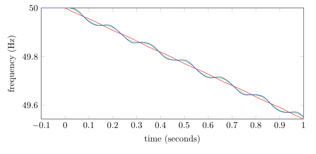
Two generator system
We started by considering a simplified system with two generators. Each generator has a local load. The two nodes of the system are separated by a transmission line. Our aim was to model and understand what would happen if one of the loads increased by 10%.
Each generator is characterised by its electrical phase angle and rotational velocity. How these quantities change in time following a load increase is typically modelled by the ‘swing’ equations for synchronous generators. The system behaviour depends on:
- the inertia of each generator
- the power being consumed by each load, which remains constant
- the power flow in the transmission line, which in turn depends on the difference between the voltage magnitudes and voltage phases at the ends of the transmission line.
Following an increase in load, the two generators will make up the shortfall in power generation by converting their kinetic energy to electrical energy, and as a consequence will slow. The rate at which each generator slows depends on its inertia. If one generator starts to slow faster than the other, the electrical coupling between the two synchronous machines will impose a force that brings the two generators back into synchronisation.
The overall frequency will continue to fall until the fuel supply rate is increased to one or both of the generators.
Three-node system
Our next model was used to investigate the behaviour of remote wind farms connected to synchronous generation and load:
- Adelaide has a load of 2000 MW and 2000 MW of synchronous generation capacity
- wind farm W1 has 1500 MW of generation capacity and no load
- wind farm W2 has 500 MW of generation capacity and no load.
We assumed no voltage losses in the transmission lines, so we did not have to model reactive power. We ignored drag on the synchronous rotors, and assumed that the load did not depend on frequency. The synchronous generators had inertial energy equivalent to 5 seconds of operation at full load; each wind generator had inertial energy equivalent to 0.5 seconds of operation at full load.
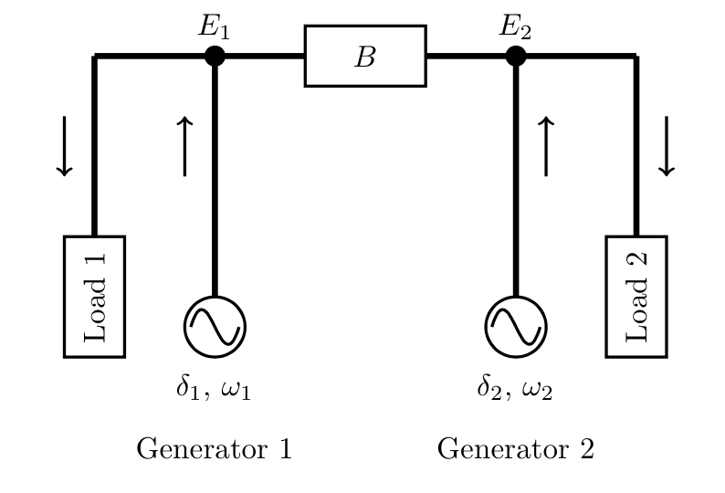
Our first test scenario had 1500 MW generated in Adelaide, 400 MW generated at W1 and 100 MW generated at W2. When the load was increased by 10%, the overall system frequency dropped at a rate of about 0.5 Hz per second, as shown in the figure below. The red curve shows the frequency of the synchronous generator; the blue and green curves show the frequency of the wind generators.
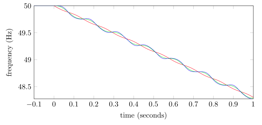
Changing the initial conditions to 500 MW generated in Adelaide, 1400 MW at W1 and 100 MW generated at W2 had little impact if the total inertia in Adelaide was left at the equivalent of 5 seconds of operation at full load. However, if the inertia in Adelaide was reduced to 1/3 of its initial value then the frequency dropped at a rate of about 1.7 Hz per second.
Other work
Delegates at MISG also:
- derived an equation for the initial ROCOF at a node, which shows that the initial ROCOF is equal to P/(ω J) where P is the increase in power, ω is the initial angular velocity and J is the inertia at the node; this means that the initial ROCOF will be higher for nodes with low inertia
- analysed the stability of a single generator connected to an `infinite bus’—a large system where the voltage and frequency do not change—and found that having too much inertia can reduce the region of stable operation; this result is also described in the literature
- derived a linear approximation for a system with many nodes, and used this model to analyse the performance of a 2-node model
- investigated how energy stored in the system, such as in batteries, can be used to stabilise frequency.
Conclusions
The behaviour of a system of synchronous generators is typically modelled using differential equations called the ‘swing’ equations. These equations are often used to predict behaviour following a sudden change in the load on a system. With these equations, the aggregated behaviour of a set of synchronous generators with individual inertias is similar to the behaviour of a single generator with aggregated inertia—summing the individual inertias is a reasonable approximation.
An advantage of having synchronous generators is that they are easy to control. Following a disturbance, each synchronous generator can be controlled independently by responding to the observed frequency ‘droop’. As long as the disturbance is not too great, the system will stabilise automatically.
New generation technologies can be more flexible in their response. If they are configured to emulate the response of a synchronous generator then it appears that they will not have a negative impact on traditional grids. With additional storage, they can emulate greater amounts of inertia. However, emulating traditional inertia is not necessarily the optimal response to a disturbance.
Contributors
We thank the MISG delegates who worked on this problem: Graham Benham, Dimetre Triadis, Julio Braslavsky, Guido Baarrdink, Mustafa Hamad, Zorica Nedic, Peter Pudney, Asbjorn Riseth, Tony Miller.